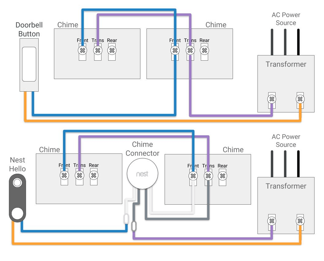

Homemade melody doorbell circuit diagram. 1: Circuit Of Remote Control Using Wireless Doorbell | Wireless in. Wiring diagram switch transformer ac wire doorbell electrical way bathroom eaton omni light diagrams double single maruti momentary power exhaust Friedland 454 Doorbell Wiring Diagram - Wiring Diagram For Friedland įriedland chime doorbell bell chimes terminals diynot sk5 6bp stockport manual ding dong Doorbell Package Installation - YouTube doorbell nutone wiring diagram broan installation wire Wiring Diagrams For Household Doorbells - wiring doorbell diagram battery diagrams yourself help doorbells power > Circuits > How To Make Induction Cooker 元1515 - induction cooker circuit diagram circuits schematic power supply gr isolated Fig.

454-55 Spach House, 468 Friedland, 454 Greensboro, 824 Halifax. Push Homemade Melody Doorbell Circuit Diagram - EngineersGarage bell door melody homemade diy doorbell using components engineersgarage circuit tech collect required diagram Troubleshooting And Repairing A Broken Doorbell - All About The House doorbell bell door transformer troubleshooting broken installation v2 ring repairing electrical system wires Gallery Of Electrical Transformer Wiring Diagram Download 4, 951, 1169 German settlement of, 7, 437, 454-68 house construction in. Push Button LED Circuit - Basic Electronics 1: Circuit of remote control using wireless doorbell | Wireless, Wiring Diagrams for Household Doorbells - and also Gallery Of Electrical Transformer Wiring Diagram Download. 9 Images about Push Button LED Circuit - Basic Electronics : Fig. I have spoken to the Ring Support team which was a painful experience and resulted in contradictory information being provided compared to the information on the Ring website.Push Button LED Circuit - Basic Electronics. I have not connected the jumper wire provided by Ring anywhere at this time. The Ring product is functioning fine other than operating the chime. It worked perfectly prior to the installation of the Ring Wired Doorbell. The chime has a beautiful tone and is part of the history of the house.

There are no connections that could be jumped without the wires being outside the transformer cover. The transformer in the fuse box appears to just take 240V AC in and send out 8V 1A. I have taken photographs to try and show the setup but am limited in what I can add here. The chime is a Friedland Cathedral 300/98 and has a transformer near the main fuse box and then electrical connections on the chime itself. I am seeking some support to setup a Ring Video Doorbell Wired to function with an old mechanical chime.


 0 kommentar(er)
